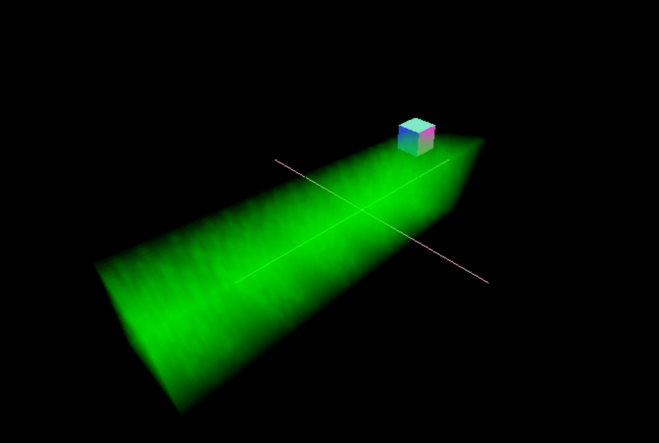
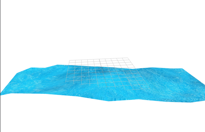
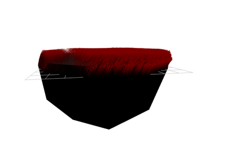
So for a long time I have wanted to do volumetric effects like ground fog or clouds again. The first thing which I think about is 3D textures and although quite well supported in WebGL2 in most major browsers. There are still some gaps. Another important point is that fractal brownian motion noise is very expe4nsive to do in a truly real time way, massively reducing the FPS.
The source for the actual slicing of a 3D texture into rows for a 2D texture is here from a stackoverflow answer. Its one of the first things which will pop up in searching for how to do this programatically.
The idea is demonstrated below:
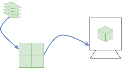
Essentially we use 3D data, slice this up into rows in a 2d Texture and then use a special function to read this 2D texture in the fragment shader on the GPU.
Just to be really clear I have only used this workaround and didnt come up with the solution. As such I wont be explaining the code, have a read around on stackoverflow and you can get an understanding of it.
Here is the volumetric rayMarching codesandbox:
So we need a few things to get this working:
- 3D noise function in Javascript and on the CPU
- Put this in a 2D texture
- A way to read this texture in a coherent way
- Ray Marching algorithm
Ill cover point 1 and 2 first together. Here is the code responsible for generating the 2D texture work around:
1const textureSize = 4;23const slicesPerRow = 3;4const numRows = Math.floor((textureSize + slicesPerRow - 1) / slicesPerRow);56const [texture] = useMemo(() => {7 // https://threejs.org/docs/#api/en/textures/DataTexture8 // https://coderedirect.com/questions/241043/3d-texture-in-webgl-three-js-using-2d-texture-workaround910 var pixels = new Float32Array(11 textureSize * slicesPerRow * textureSize * numRows * 412 );13 var noiseRaw = new Noise(0.1);14 var pixelsAcross = slicesPerRow * textureSize;15 for (var slice = 0; slice < textureSize; ++slice) {16 var row = Math.floor(slice / slicesPerRow);17 var xOff = (slice % slicesPerRow) * textureSize;18 var yOff = row * textureSize;19 for (var y = 0; y < textureSize; ++y) {20 for (var x = 0; x < textureSize; ++x) {21 var offset = ((yOff + y) * pixelsAcross + xOff + x) * 4;22 const freq1 = 0.9;23 const freq2 = Math.random();24 const freq3 = Math.random();25 const noise3D1 = noiseRaw.perlin3(y * freq1, slice * freq1, x * freq1);26 const noise3D2 = noiseRaw.perlin3(y * freq2, slice * freq2, x * freq2);27 const noise3D3 = noiseRaw.perlin3(y * freq3, slice * freq3, x * freq3);2829 pixels[offset + 0] = noise3D1 + noise3D2 + noise3D3;30 pixels[offset + 1] = noise3D1; // + noise3D2 + noise3D3;31 pixels[offset + 2] = noise3D1; // + noise3D2 + noise3D3;32 pixels[offset + 3] = noise3D1; // + noise3D2 + noise3D3;33 }34 }35 }36 const width = textureSize * slicesPerRow;37 const height = textureSize * numRows;3839 const texture = new THREE.DataTexture(40 pixels,41 width,42 height,43 THREE.RGBAFormat,44 THREE.FloatType45 );4647 texture.minFilter = THREE.LinearFilter;48 texture.magFilter = THREE.LinearFilter;4950 texture.needsUpdate = true;5152 return [texture];53}, [numRows]);
So we generate the neccessary data using noisejs. You use it like so:
1var noiseRaw = new Noise(0.1);23const noise3D1 = noiseRaw.perlin3(y * freq1, slice * freq1, x * freq1);
One way to get interesting shapes is to mix different frequencies of noise and youd be suprised with the various shapes you can generate!
Also we have to do this as for some reason beyond my current understanding of noise, if you provide whole integers you will get 0 from this noise function.
I have read multiple times this is actually what is to be expected with the whole number inputs for x, y and z.
Then dataTexture is used which is where we can use custom data and generate a texture we can pass to the shaders as a uniform.
The code in the stackoverflow answer to use in the shaders in GLSL is below:
1uniform float uSize;2uniform float u_numRows;3uniform float u_slicesPerRow;45vec2 computeSliceOffset(float slice, float slicesPerRow, vec2 sliceSize) {6 return sliceSize *7 vec2(8 mod(slice, slicesPerRow),9 floor(slice / slicesPerRow)10 );11}1213vec4 sampleAs3DTexture(14 sampler2D tex,15 vec3 texCoord,16 float size,17 float numRows,18 float slicesPerRow19) {20 float slice = texCoord.z * size;21 float sliceZ = floor(slice); // slice we need22 float zOffset = fract(slice); // dist between slices2324 vec2 sliceSize = vec2(1.0 / slicesPerRow, // u space of 1 slice25 1.0 / numRows); // v space of 1 slice2627 vec2 slice0Offset = computeSliceOffset(sliceZ, slicesPerRow, sliceSize);28 vec2 slice1Offset = computeSliceOffset(sliceZ + 1.0, slicesPerRow, sliceSize);2930 vec2 slicePixelSize = sliceSize / size; // space of 1 pixel31 vec2 sliceInnerSize = slicePixelSize * (size - 1.0); // space of size pixels3233 vec2 uv = slicePixelSize * 0.5 + texCoord.xy * sliceInnerSize;34 vec4 slice0Color = texture2D(tex, slice0Offset + uv);35 vec4 slice1Color = texture2D(tex, slice1Offset + uv);36 return mix(slice0Color, slice1Color, zOffset);37 return slice0Color;38}
Now we have a way of reading the texture which has the 3D noise in But we also need a rayMarching algorithm. Below is the shell of the algorithm:
1// MiN/Max for inside bounding box2float value = 2.0;3float xMin = -2.0;4float xMax = 2.0;5float yMin = -2.0 ;6float yMax = 2.0;7float zMin = -10.0;8float zMax = 10.0;910bool insideCuboid (vec3 position) {11 float x = position.x;12 float y = position.y;13 float z = position.z;14 return x > xMin && x < xMax && y > yMin && y < yMax && z > zMin && z < zMax;15}1617void main() {18 vec2 uv =( gl_FragCoord.xy * 2.0 - (uResolution - vec2(0.5,0.5)) ) / uResolution;19 vec2 p = gl_FragCoord.xy / uResolution.xy;2021 vec2 screenPos = uv;2223 vec3 ray = (cameraWorldMatrix * cameraProjectionMatrixInverse * vec4( screenPos.xy, 1.0, 1.0 )).xyz;24 ray = normalize( ray );2526 vec3 cameraPosition = camPos;27 vec3 rayOrigin = cameraPosition;28 vec3 rayDirection =ray;2930 vec3 sum = texture(tDiffuse, p).xyz;31 float rayDistance = 0.0;32 float MAX_DISTANCE =20.0;33 vec3 color = vec3(0.0,1.0,0.0);3435 for (int i = 0; i< 1000;i ++) {36 vec3 currentStep = rayOrigin + rayDirection * rayDistance ;3738 bool insideBoundries = insideCuboid(currentStep);3940 float density = 0.9;41 float trans = 0.03;4243 if ( insideBoundries ) {44 for (int i = 0; i< 2; i++) {45 float distance = length(currentStep);46 float s = sampleAs3DTexture(noiseSample, currentStep + uTime, uSize, u_numRows47 ,u_slicesPerRow).r;4849 if ( 0.1003 < abs(s)) {50 density += abs(s);51 }5253 if (density > 1.0) {54 break;55 }56 }57 sum = mix(sum, color, density * trans );58 }59 if (rayDistance > MAX_DISTANCE) {60 break;61 }62 rayDistance += 0.1;63 }646566 gl_FragColor = vec4(sum.xyz, 1.0);67}
We first of all need a ray in the right coordinates and to rotate with the screen as we move the camera:
1vec3 ray = (2 cameraWorldMatrix *3 cameraProjectionMatrixInverse *4 vec4( screenPos.xy, 1.0, 1.0 )5).xyz;
Here are the variables we setup for rayMarching:
1vec3 cameraPosition = camPos;2vec3 rayOrigin = cameraPosition;3vec3 rayDirection =ray;45vec3 sum = texture(tDiffuse, p).xyz;6float rayDistance = 0.0;7float MAX_DISTANCE =20.0;8vec3 color = vec3(0.0,1.0,0.0);
Firstly we have to have an origin to the ray, which is the camPos. Then a direction to fire the ray in (which is derived from uv’s… a good explanation is in this stackoverflow answer refering to a shaders gl_FragCoord’s and uv’s).
We have a sum of rayMarching colors and base or background textures. Setting this to be the initial scenes texture.
We have a max distance so the rays dont go on forever and waste resources.
And then a base color for the clouds:
1vec3 color = vec3(0.0,1.0,0.0);
Below is the bulk of the rayMarching code:
1for (int i = 0; i< 1000;i ++) {2 vec3 currentStep = rayOrigin + rayDirection * rayDistance ;34 bool insideBoundries = insideCuboid(currentStep);56 float density = 0.9;7 float trans = 0.03;89 if ( insideBoundries ) {10 for (int i = 0; i< 2; i++) {11 float distance = length(currentStep);12 float s = sampleAs3DTexture(noiseSample, currentStep + uTime, uSize, u_numRows13 ,u_slicesPerRow).r;1415 if ( 0.1003 < abs(s)) {16 density += abs(s);17 }1819 if (density > 1.0) {20 break;21 }22 }23 sum = mix(sum, color, density * trans );24 }25 if (rayDistance > MAX_DISTANCE) {26 break;27 }28 rayDistance += 0.1;29}
We do a initial for loop which dictates the max iterations we might do in increasing the rays length:
1for (int i = 0; i< 1000;i ++) {2 // marching code here3}
We have a break keyword here:
1if (rayDistance > MAX_DISTANCE) {2 break;3}
This will ensure we dont carry on these rays for ever and cause our computers to crash or run very slowly 🥵.
We then do some calculations for density:
1float density = 0.9;2float trans = 0.03;34if ( insideBoundries ) {5 for (int i = 0; i< 2; i++) {6 float s = sampleAs3DTexture(noiseSample, currentStep + uTime, uSize, u_numRows7 ,u_slicesPerRow).r;89 if ( 0.1003 < abs(s)) {10 density += abs(s);11 }1213 if (density > 1.0) {14 break;15 }16 }17 sum = mix(sum, color, density * trans );18}
Now this code is me playing around with things alot to see what works best.
But the gist is the greater the density turns out to be… the greater we end up with raymarched color as we use the density to mix the original background textures color with the rayMarched colour vec3(0.0, 1.0, 0.0).
If we are inside the cuboid then we do ray marching if not we dont. We run this code every time we increase the current step of the ray (firing into 3D space):
1vec3 currentStep = rayOrigin + rayDirection * rayDistance ;23bool insideBoundries = insideCuboid(currentStep);
Then when inside the cuboid we sample 3 more times adding to the density each time:
1for (int i = 0; i< 2; i++) {2 float s = sampleAs3DTexture(3 noiseSample,4 currentStep + uTime,5 uSize,6 u_numRows7 ,u_slicesPerRow8 ).r;910 if ( 0.1003 < abs(s)) {11 density += abs(s);12 }1314 if (density > 1.0) {15 break;16 }17 // more code...18}
The abs(s) is because a noise value could have been negative here, you could also do this in the javascript code.
So this is where the noise comes in, we sample the 2D texture using a moving vector to mimic movement in the final rendered 3D texture:
1currentStep + uTime
So at each step we sample we get a noise value. Now heres the magical part, how does it know where the edges or the texture are in 3D space. Wrapping types to the rescue, here is the texture docs in threejs.
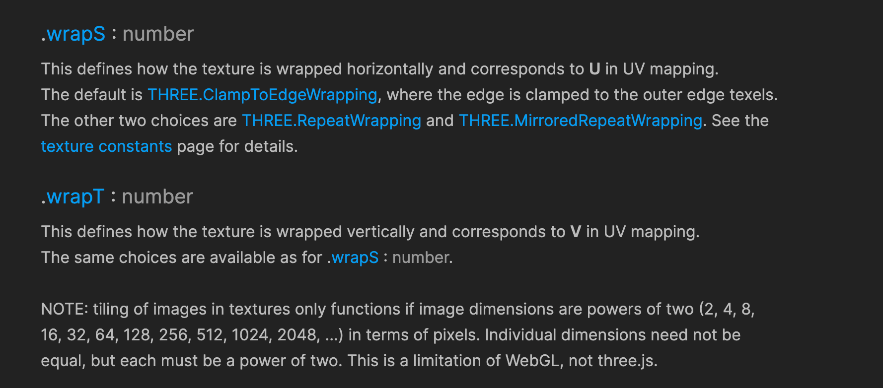
And here is where we set the wrapping of the texture:
1useFrame((state) => {2 texture.wrapS = texture.wrapT = THREE.MirroredRepeatWrapping;3 // more code...4}
When we set this, it doesnt matter how far the ray goes into 3D space it just mirrors the texture when it would have normally been out of bounds.
You can also clamp the texture to the edges and there’s several other wrap types aswell.
Magic eh 😉 (not quite haha).
And then at the end of the initial for loop we do this as stated before:
1if (rayDistance > MAX_DISTANCE) {2 break;3}4rayDistance += 0.1;
Check max distance and if not reached then we increment the distance the ray has travelled.
I know for a fact there are short circuits or better ways of optimizing the incrementing of the ray. But this is a POC and me playing around with things.
All of this is me experimenting with things and wont be optimized as much as it could be.
The final bit of the code is this:
1vec3 sum = texture(tDiffuse, p).xyz;23 // more code...45 sum = mix(sum, color, density * trans );67 // more code...89 gl_FragColor = vec4(sum.xyz, 1.0);10}
We set the vec3 sum to be the background texture which will be the scene with everything in before the post processing took place.
This is mixed with cloud or fog colour using the density. We multiply this cumulative density with a transmittance factor. Why do we do this? as every material transmits a certain percentage light nothing transmits 100% light, there is always absorption, apart from black holes ⚫ haha
And finally we set the sum or mixture of both colours as gl_FragCoord which is the output value of the fragment shader.
Final Thoughts
This is a volumetric rendering technique, although basic it gives you an idea of how to accomplish this in a R3F way.
One way to make this more interesting is to mix the noise in the 2D texture with a real time noise value to mask the repetition which will inevitably show when using a pre computed texture of noise.
Also as an experiment you could create a 3D vector field which would be used in the direction of movement for the original noise.
Lots to build on here, but its a good start in trying to understand and implement volumetric rendering in real time.
Thanks for reading 🙂!

